


- Capabilities
-
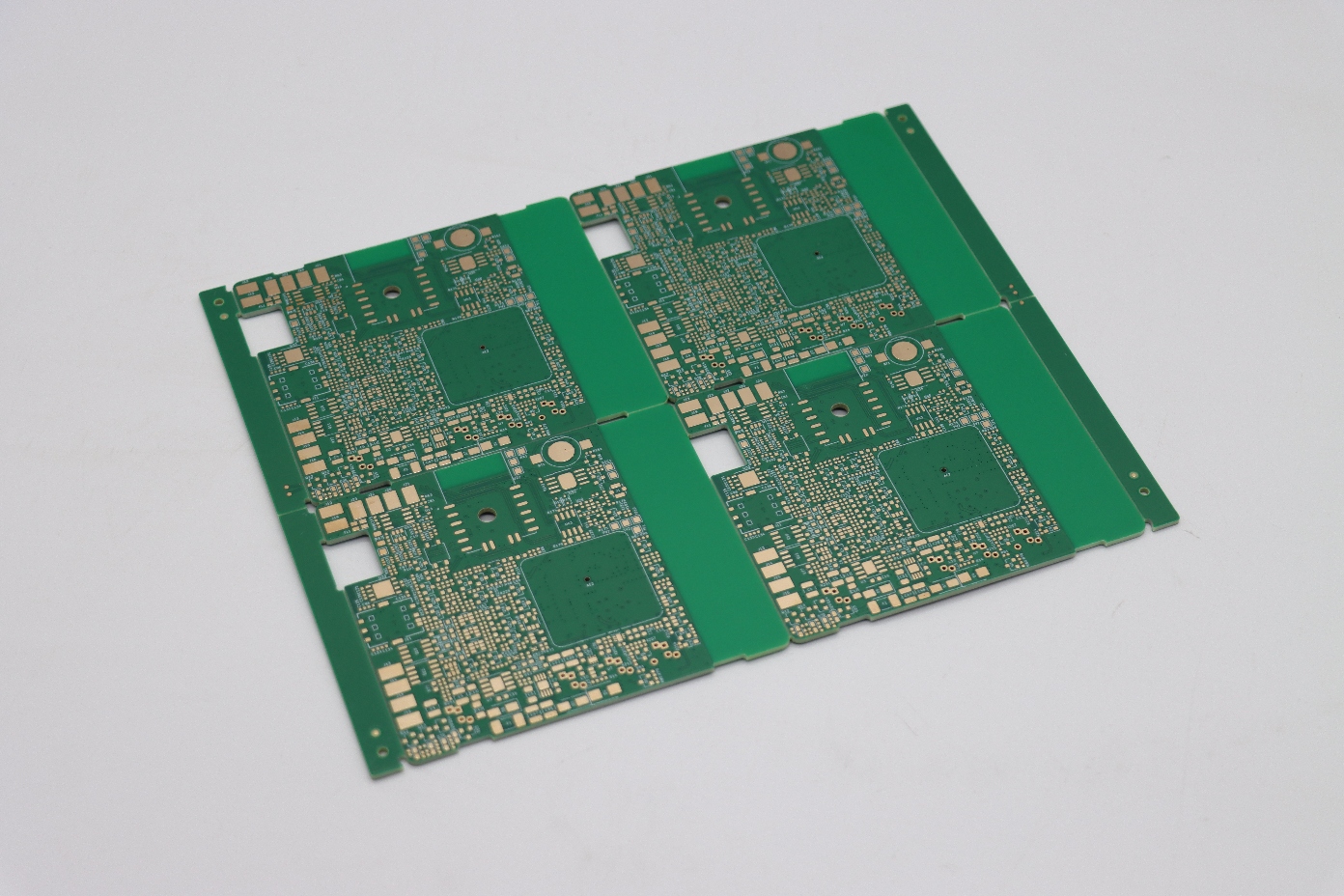
FR-4 PCB

-
Aluminum PCB
-
Copper PCB
- Capabilities
-
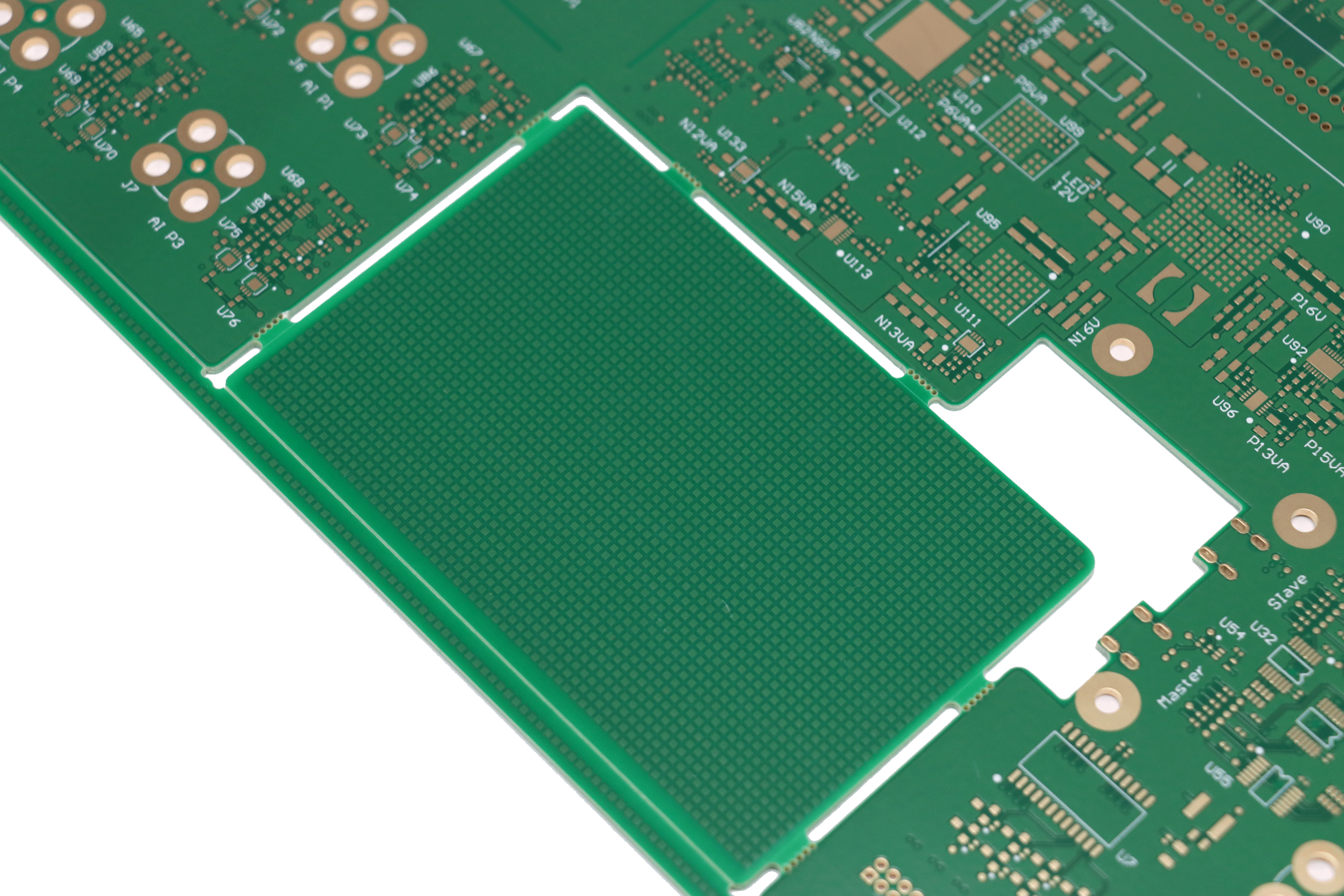
Advanced PCB
-
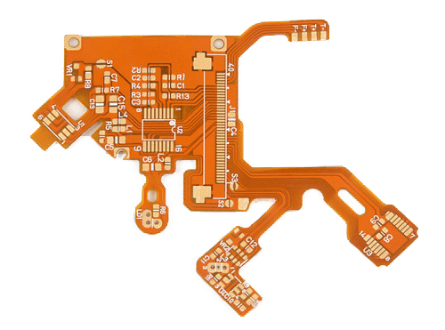
Flexible board
-
Rigid-Flex PCB
-
PCB Assembly
- Resources
-
Blog
-
News
-
Help Center
-
Payment Methods
-
Shipping Methods
- Why WEEQOO
-
About Us